The information contained in this document are recommendations on how to make ShaeFiles (.shp) that allow automation of the creation of 3D buildings in RhinoCityTM, and their export to the CityGML format.
The files to be supplied are three, one of wich is optional:
•File n°1 : contains the building footprints,
•File n°2 OPTIONAL : contains the building subsets footprints
•File n°3 : contains the roof elements,
Following are the detailed properties for the creation of these 3 files.
The building footprints file
File name
The file name must have the suffix « _Building ».
For example, a valid name for a ShapeFile file is: RC_Building.shp
Warning The user-chosen prefix should be the same for all files. In the above example, since « RC » is the chosen prefix, the associated ShapeFile files names will be: RC_BuildingPart.shp and RC_Roofprint.shp
Geometry
The ShapeFile file should contain only PolygonZ type geometry elements. The polygons may be of MultiParts type.
Attribute scheme
The attribute scheme is composed of 5 attributes:
Name |
Type |
Default value |
Description |
BUILDINGID |
String |
|
Unique identifier of the building |
ZMIN |
Double |
0.0 |
Elevation of the lowest point of the building |
TEXTURE |
Integer |
1 |
Specify if the building must be textured (1) or not (0) |
THICKNESS |
Double |
0.10 |
Thickness of roof overhangs (in meter units) |
OVERHANG |
Integer |
0 |
Specify if the roofs overhangs must be computed (1) or not (0) |
BUILDINGID
BUILDINGID is the unique identifier of the building.
Warning Inside the ShapeFile, the identifier « BUILDING » of each building must be unique.
During a CityGML export, its value will be the one used to identify the building through the CityGML attribute “gml:id” of the object “bldg:Building”.
This attribute is present in the attribute scheme of building footprint file described here, as well as in building roof element file described later in this document. It is the key value that allows the footprint and the roofprint of an individual building to be linked.
ZMIN
ZMIN is the altitude of the lowest point of the building.
TEXTURE
TEXTURE is an attribute used during the rendering phase of a 3D model, specifying if a building must be textured or not. A new building that would not appear on an aerial image should not be textured. In this case, the value of its «TEXTURE » attribute should be set to 0. The default «TEXTURE» value is 1 for all polygons.
THICKNESS
THICKNESS is the theoretical thickness of the roof overhangs in meters. Used only during the 3D rendering of buildings, it can be initialized at 0.10 when creating ShapeFiles.
OVERHANG
OVERHANG is an attribute used to specify if the building roofs overhangs must be computed. The default OVERHANG value is 0 for all buildings (=not computed).
ADDITIONAL ATTRIBUTES
At least the 5 attributes described above must be present; the model may have additional attributes chosen by the user.
Note: these additional attributes will also be exported in a CityGML file by RhinoCityTM.
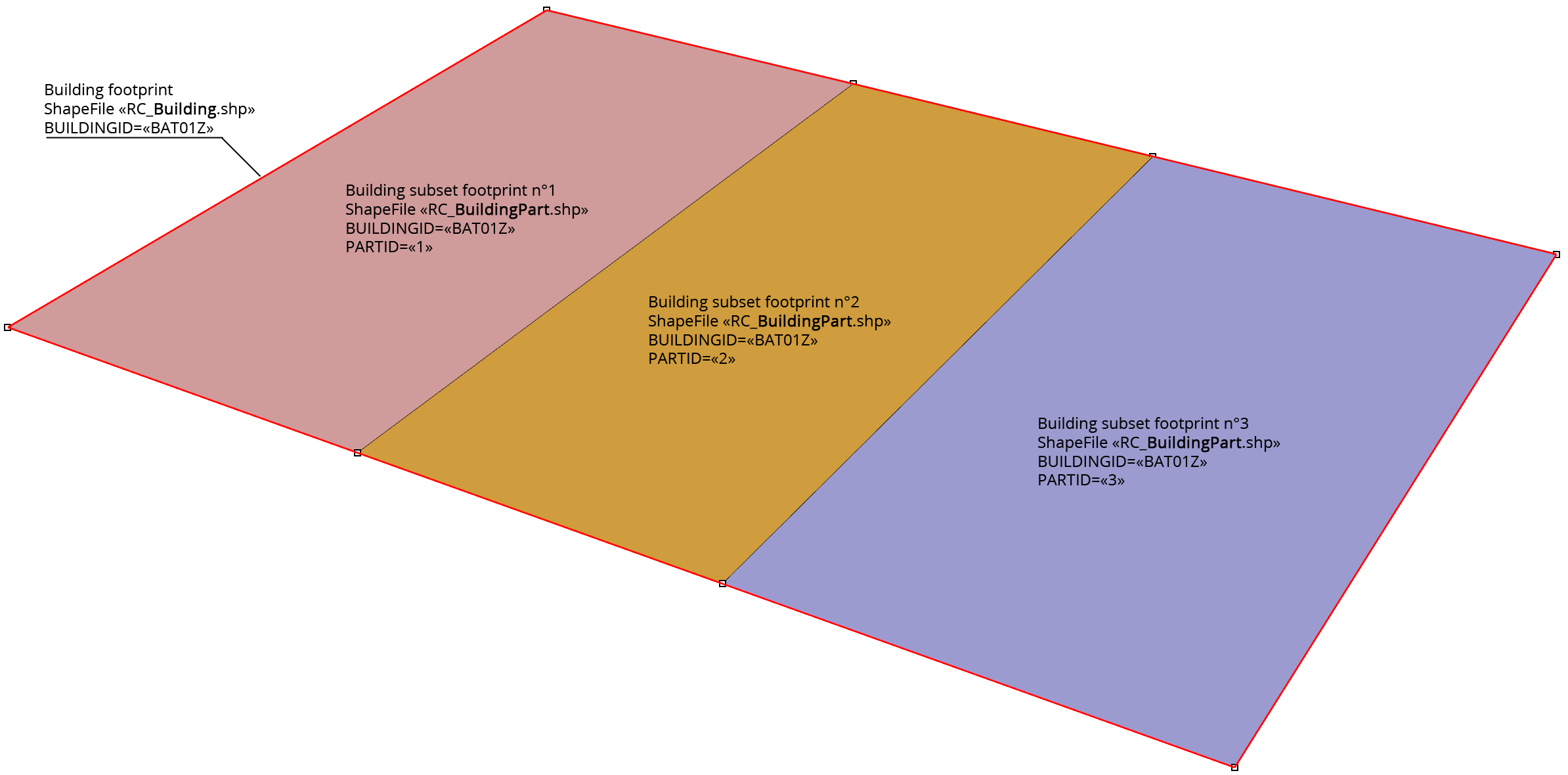
The building subsets footprints file
The concept of a building subset allow a more detailed 3D modeling of the buildings, both from a geometrical point of view and from a semantic point of view. Its implmentation allow :
•a better restitution of the discontinuities of the different roof heights that can exist within the same building. This makes it possible, for example, to be able to provide each roof area with overhanging eaves.
•a differentation of the attribute scheme of th building subsets from the attributes scheme of the building itself.
•
Important This file is optional. If you do not want split your buildings into building subsets, this file is not required. If it does not exist, modeling is equivalent to considering that each building consists of a single building subset.
File name
The file name must have the suffix « _BuildingPart ».
For example, a valid name for a ShapeFile file is : RC_BuildingPart.shp
Warning The user-chosen prefix should be the same for all files. In the above example, since « RC » is the chosen prefix, the associated ShapeFile files names will be: RC_Building.shp and RC_Roofprint.shp
Geometry
The ShapeFile file should contain only PolygonZ type geometry elements. The polygons may be of MultiParts type.
Warning The union of the different polygons of the building subsets must be equal to the polygon of the building footprint.
Attribute scheme
The attribute scheme is composed of 4 attributes:
Name |
Type |
Default value |
Description |
BUILDINGID |
String |
|
Unique identifier of the building |
PARTID |
String |
|
Unique identifier of the building subset |
ZMIN |
Double |
0.0 |
Elevation of the lowest point of the building subset |
THICKNESS |
Double |
0.10 |
Thickness of roof overhangs (in meter units) |
BUILDINGID
BUILDINGID is the unique identifier of the building.
PARTID
PARTID is the unique identifier of the building subset.
Warning Inside a building having an unique identifier « BUILDINGID », each subset of this building must have a unique « PARTID » identifier.
ZMIN
ZMIN is the altitude of the lowest point of the building.
THICKNESS
THICKNESS is the theoretical thickness of the roof overhangs in meters. Used only during the 3D rendering of buildings, it can be initialized at 0.10 when creating ShapeFiles.
Note When ShapeFile « BuildingPart » is used, attributes values ZMIN and THICKNESS of the building subset are the one used, in place of the building attributes values potentially filled (cf. attribute scheme for « BUILDING » ShapeFile, attributes ZMIN, and THICKNESS).
ADDITIONAL ATTRIBUTES
At least the 5 attributes described above must be present; the model may have additional attributes chosen by the user.
Note : these additional attributes will also be exported in a CityGML file by RhinoCityTM.
The building roofprints file
File name
The file name must have the suffix « _Roofprint ».
For example, a valid name for a ShapeFile file with building footprints is: RC_Roofprint.shp
Warning The user-chosen prefix should be the same for all files. In the above example, since « RC » is the chosen prefix, the associated ShapeFile files names will be: RC_Building.shp et RC_BuildingPart.shp
Geometry
The ShapeFile file should contain only PolygonZ type geometry elements. The polygons may be of MultiParts type.
Attribute scheme
The attribute scheme is composed of 7 attributes:
Name |
Type |
Default value |
Description |
BUILDINGID |
String |
|
Unique identifier of the building |
PARTID |
String |
|
Unique identifier of the building subset |
CONSTRID |
Integer |
|
Construction identifier of a roof element |
ZEXTRUSION |
Double |
0.0 |
Extrusion value of a roof element |
ROOFTYPE |
Integer |
0 |
Type of a roof element |
OPERATOR |
Integer |
0 |
Element must be : 0=added, 1=subtracted |
CANBECUT |
Integer |
1 |
Element must be : 0=overhung, 1=cutted |
BUILDINGID
BUILDINGID est l’identifiant unique du bâtiment.
PARTID
PARTID is the unique identifier of the building subset.
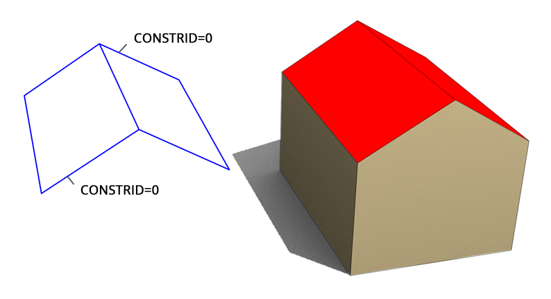
CONSTRID
CONSTRID is the part construction identifier of a roof element. This identifier is used to make a “logical” grouping of several of these elements when they make up a characteristic set of the different roof parts.
|
Example n°1 : Two roof elements, a unique characteristic feature set, therefore one single ID: CONSTRID = 0 |
||
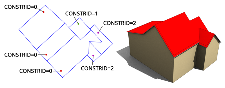
Example n°2 : six roof elements, three characteristic feature sets, therefore three ID’s: CONSTRiD = 0, 1 et 2
|
|
||
|
|||
|
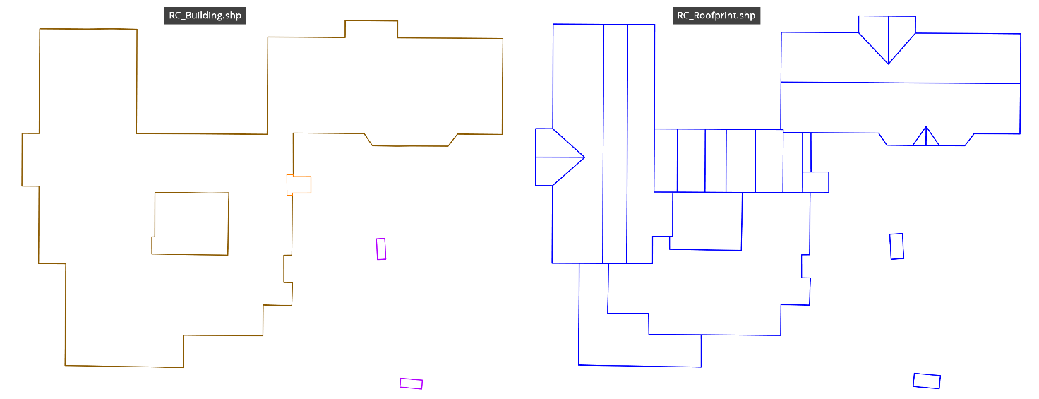
Example n°3 : PolygonZ « Multiparts » made of - a main outline with “hole” (brown) - secondary outline n°1 (orange) - secondary outline n°2 (magenta), itself consisting of two outlines |
||
ZEXTRUSION
ZEXTRUSION defines the extrusion value of the roof elements.
If the value of « ZEXTRUSION » is 0.0, when creating the 3D building ,the extrusion will be up to the minimum building height (the ZMIN attribute value of attribute scheme of the building footprints ShapeFile.
Remarques :
1)roof elements having the same « CONSTRID » must have identical « ZEXTRUSION » values.
2)If the value of « ZEXTRUSION » is not 0.0, the extrusion will be treated as a relative value, ie, a 3D offset from the polygon with this attribute, starting from his elevation. In this case, the extrusion will be lowered if value is negative, raised if value is positive.
ROOFTYPE
Useful for export to the CityGML format, « ROOFTYPE »distinguishes the main roof elements named « MainRoof » from the related structures named « Outer Installations ».
•RoofType = 0 for the main elements « MainRoof »
•RoofType = 1 for related structures « Outer Installations »
OPERATOR
OPERATOR makes it possible to specifi whether a roof element is added to the others in order to constitute the final solid, or on the contrary, if it withdraws.
The default value of this attribute is 0 : every element is « added ». If value is 1, then the element is subtracted.
CANBECUT
CANBECUT is an attribute that indicates whether an element must be « overhung » or « cut » by the other elements.
By default, the value of this attribute is 1, that is, any element is by default « cutted ».
ATTRIBUTS COMPLEMENTAIRES
At least the 5 attributes described above must be present; the model may have additional attributes chosen by the user.
Note : these additional attributes will also be exported in a CityGML file by RhinoCityTM.
ExAmple
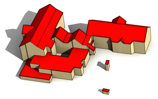
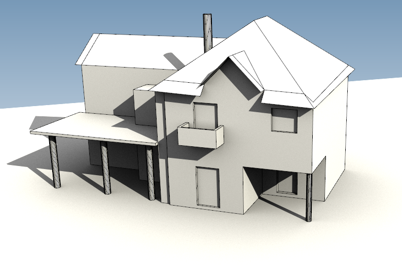
The combined action of the values of the ZETRUSION, OPERATOR and CANBECUT attributes allows the automatic production of 3D models similar to the following :
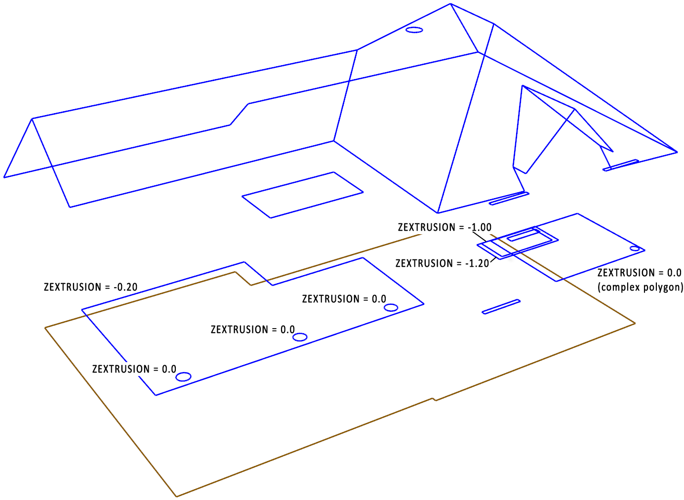
Some examples of the value of the ZETRUSION attribute
To understand both the definition of ShapeFile features classes and the attributes values used to generate this building, the sample file can be downloaded here : BldgLOD3.3dm
Qualité de la géométrie
The following rules must be observed concerning geometry quality:
ΠClosed
All polygons must be « closed » respecting the rule “first point = last point”
Uniqueness of points
A polygon may not contain any “duplicate points”
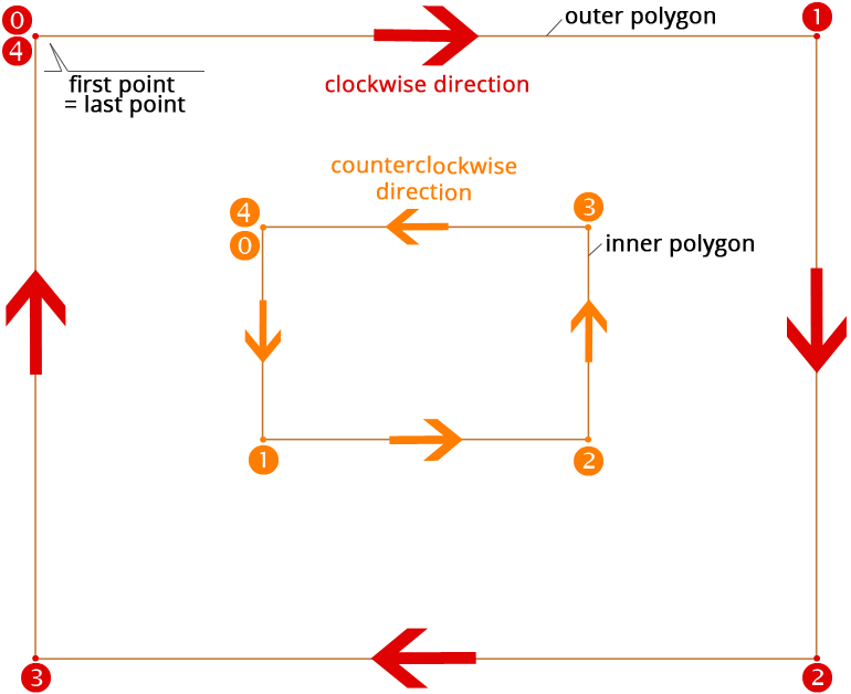
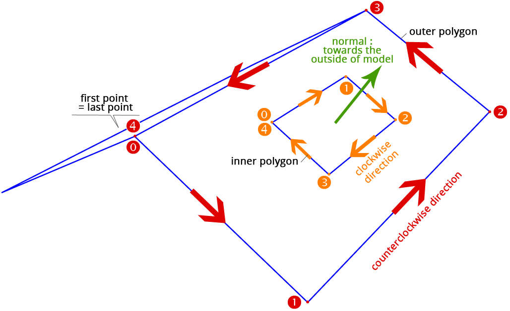
Ž Sens de parcours des polygones
“Building” and « BuildingPart » ShapeFile Polygons
An outer polygon in the “Building” ShapeFile should be described in a “clockwise” direction.
Conversely, an inner polygon (a “hole”) in the “Building” ShapeFile should be described in a “counterclockwise” direction.
Simply stated, outer and inner polygons must have opposite path directions.
ShapeFile ”Roofprint” Polygons
An outer polygon from the “Roofprint” ShapeFile should be described in a “counterclockwise” direction.
Conversely, an inner polygon (a “hole”) in the “Roofprint” ShapeFile should be described in a “counterclockwise” direction.
Simply stated, outer and inner polygons must have opposite path directions.
Note: if the above rules are respected, the normal of the plane formed by this polygon will point towards the outside of the model. This is essential for the 3D rendering during the texturing phase.
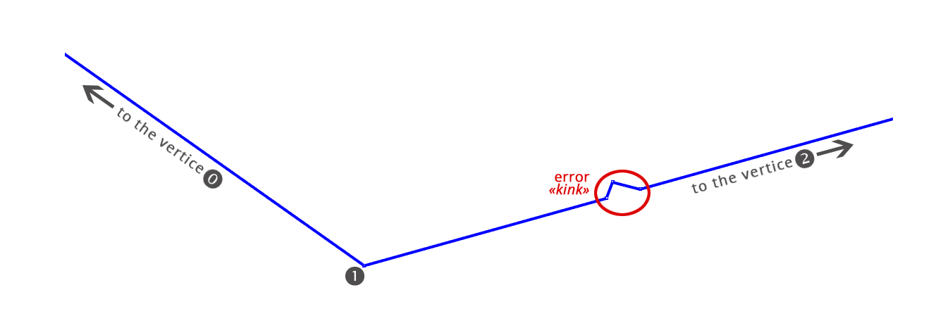
Coplanarity
A polygon must be « coplanar »
The set of vertices of a polygon must be coplanar: they must not deviate from tolerance “T” once projected onto the average plane they define.
A value of 1 centimeter is commonly accepted for the tolerance “T” mentioned above, but this a value may be defined differently according to the needs of the user.
Note: the polygon sides must not contain any “kinks” (or “bends”) - even if they are within the coplanarity tolerance “T”.
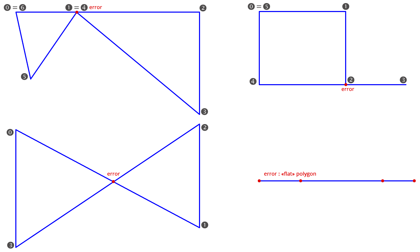
No « self-intersecting polygons »
Here are some examples of unauthorized « self-intersecting » polygons:
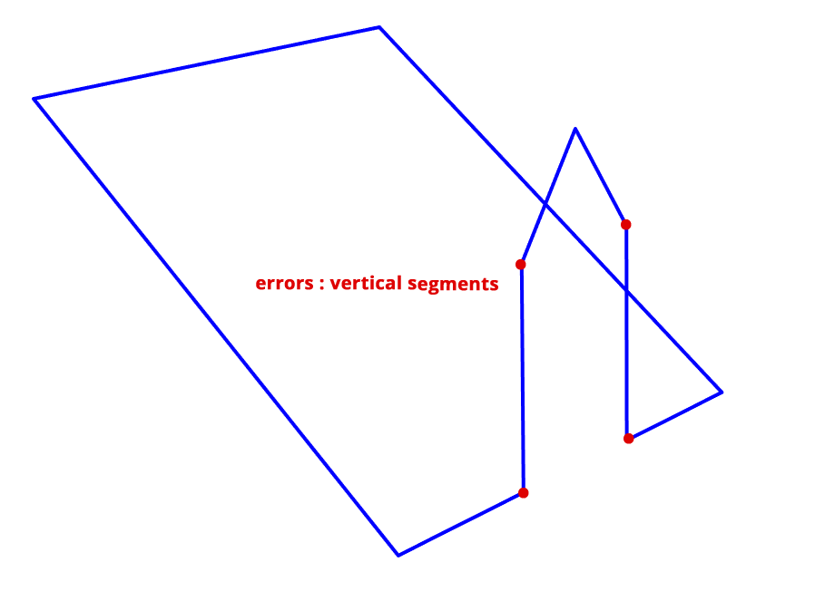
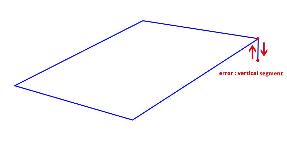
‘ No vertical segments allowed
An illegal vertical segment in the polygon may come from a mistake during mouse picking (double-click in XY with different Z values) or because a roof element has been entered or selected incorrectly.
’ Coordinate precision
Equal points must have strictly equal coordinates, without any possible tolerance. In other words, the coordinates of 2 equal points must be identical to “n” decimal digits: all expressed digits are significant.
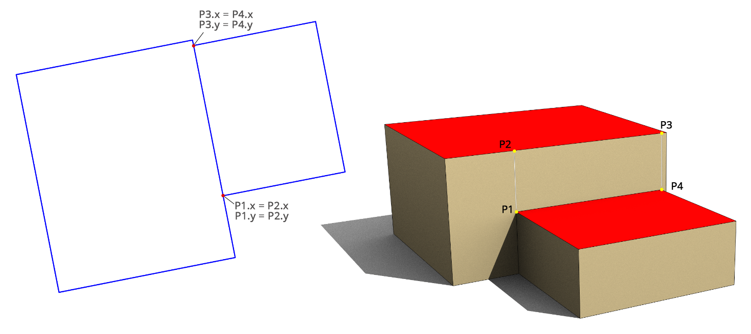
“ « Snapping »
If they have different Z values, two overhanging points across two contiguous geometries must be strictly equal in both abscissa (X) and ordinate (Y).
” Arc tessellation and minimum distance between points
The tessellation (conversion to line segments) of an arc should not produce segments of length less than 10 cm.
Note: if the original image resolution used for the photogrammetric entry is 10cm per pixel, it’s virtually impossible to get computed points separated by a distance less or equal to the one represented by one pixel.
Aside from the case of arcs, any two distinct points of the model must be separated by a distance larger than the tolerance that will be accepted by automatic “re-snapping” tools. Otherwise, there is a risk of automatic “absorption” (elimination) of some of the points, which may be detrimental to the 3D model rendering. This tolerance is defined by the user.
The information contained in this document is RhinoTerrainTM property. Disclosure to third parties or reproduction in any form whatsoever without written consent is forbidden.